There are many reasons for the difficulty of boring. The key is that the following four points need to be paid attention to. In order to facilitate the correct analysis of the problem and avoid using the wrong processing method, it is recommended that you keep it in your mind and understand it.
1 Processing of tool rotation.
① During the machining process, the condition of the tool tip cannot be observed, so it is impossible to adjust the cutting amount according to the machining condition. Ordinary lathes can be adjusted directly, and CNC lathes can be adjusted with only a button on the controller. The adjustment is simple and can be adjusted in a short time.
However, the processing of tool rotation cannot be adjusted directly, nor can it be adjusted on the CNC machine tool controller. These are one of the biggest obstacles to automated production.
②Because the machining center cannot adjust the diameter of the boring hole functionally, each boring bar must have a fine-tuning mechanism. During finishing, there must be a fine-tuning mechanism with micron-level (μm) adjustment ability according to the hole diameter tolerance. This kind of boring tool corresponds to The price of the tool is more expensive. Regrettably, due to tool costs, some users have been dragging on the issues that should be dealt with as soon as possible, and even more so, there are many cases of high hang-ups that have nothing to do with them.
③Due to the continuous change of the chip discharge direction, the cooling of the tool tip and workpiece and the processing of chips are much more difficult than lathe processing. Especially the rough boring of blind holes of steel parts on vertical machining centers is still a big problem.
2 Single-ended fixed processing.
Only the taper shank end is fixed on the machining center. Although this is no different from lathe machining, on the machining center, one aperture corresponds to one boring tool. It is necessary to understand what characteristics each boring tool has. On the basis of its characteristics, the cutting amount and feed are adjusted accordingly.
On the lathe, as long as the conditions permit, one boring bar can be used for multiple processing, so it is much easier to grasp the characteristics of the boring tool compared with the machining center. When using a machining center for boring, it is usually impossible to complete such detailed data accumulation, so it is more difficult to deal with problems when they occur.
Why is boring so difficult?
3 The rigidity of the workpiece and fixture has a great influence.
No matter what the occasion, some people choose cutting parameters based on the tool tip-centered theory. In fact, it is far from simple. Especially it is not the boring tool but the vibration and deformation of the workpiece. This situation is more. At this time, it is very difficult to select cutting parameters and choose the tool tip in combination with these conditions. At the same time, it is necessary to consider the tolerance accuracy requirements of finishing. .
4 Use ATC for tool change.
Here we need to mention the problem of the taper fit between the spindle and the tool holder. For example, the taper accuracy error of 0.2~0.5μm has an impact of 5-10μm on the tip of the boring tool. Therefore, the spindle taper accuracy of the machining center is the same as the taper of the boring tool holder. The fit of the handle accuracy is also a very important issue.
This makes changing the tool through ATC, because it is different from manual tool installation, the foreign matter and chip problems in the taper will affect the accuracy of each boring tool holder, and it will be more troublesome to handle.
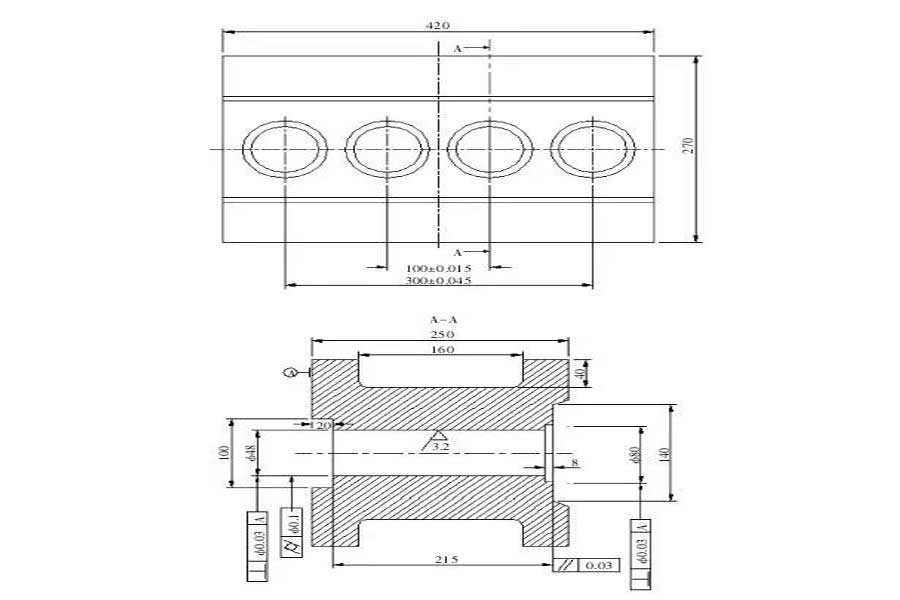
Deep hole boring processing has always been a problem in mechanical and mold processing. Before, a classmate encountered a 48×215mm deep hole processing on a hose mold. I hope to write down the pits he traveled and provide you with Some help and reference.

1. Part drawing analysis and process planning
Part drawing analysis
Figure 1 shows the parts of the hose mold. There are 4 holes 48×215mm in diameter to be processed. The external dimension is 420×270×250mm. There are 4 grooves on the top, bottom, left, and right. The hole surface has steps, and both sides have inclined surfaces as the matching surfaces.
The size of the part is shown in the figure. The process requirement of this part is that the taper of the hole cannot exceed 0.1mm, the surface roughness value is Ra3.2μm, the tolerance of the hole pitch cannot exceed 0.03mm, and the perpendicularity is 0.03mm. This mold product It is a glass hose with a wall thickness of only 0.8mm. Customers require that the thickness exceeds 0.8mm and will not be accepted. It can be said that the thinner the better, just to save costs.
At that time, I really had no idea about such difficult parts. Although our company was only responsible for processing deep cavity boring, customers could cooperate in other aspects. After many attempts, a set of simple and reasonable processing schemes have been developed.
Process planning
Simple processing sequence before part boring
After the fine material comes back, the milling machine first processes the grooves on both sides, as shown in Figure 1, the positions B and E are rough and then refined, and the number is processed.
The step on the front side of the processing is thickened, leaving a margin of 0.5mm on one side, as shown in Figure 1 at A and F.
The steps on the processing bottom surface are thickened, leaving a margin of 0.5mm on one side, as shown in Figure 1 at C and D.
Then re-install and calibrate the table, divide the four sides into the center, and process and position the center drill. Step by step, use a drill with a diameter of 10 mm, a diameter of 24 mm, and a diameter of 35 mm. Finally, use a drill with a diameter of 44 mm to drill through.
After completion, go to the surface and bottom of the large water mill, as shown in Figure 2, and grind to a few to ensure that the parallelism is 0.03mm.
As shown in Figure 1, 0.3mm fine machining allowance is reserved for side grinding of B and E.
Clamping and positioning datum of parts
The workpiece is directly clamped on the numerical control workbench, and the 4 die feet are respectively tightened, and the calibration is centered, and the error is controlled within 0.03mm.
2. Parts CNC machining
Part drawing analysis
Self-made boring tool: First make a self-made boring tool holder as shown in Figure 3, the material is 837H, first rough turning, reserve 0.5mm margin, after heat treatment, use a cylindrical grinder to process, the focus is to ensure the coaxiality. The small knife holder with inserts buys standard parts of 10×10mm, which is convenient for changing the blades and guarantees the size.
The inclination angle of the built-in small tool holder is 20°, and it is processed by wire cutting and is slightly tightly fitted. The boring tool holder is drilled with M6mm hexagon socket screws, and the small tool holder is locked with the hexagon socket screws. The standard small tool holder is equipped with cemented carbide blades, the entering angle is 30°, the flank avoiding angle is 15°, and the blade tip has an angle of R0.3~R0.4mm to minimize the contact surface to prevent vibration.
Processing plan determination
Hole processing plan 1
It is the most straightforward and simple method to use fast-moving thread cutting. However, because the size is too deep to be 215mm, it is difficult to solve the cooling and flushing during processing, and it is easy to break the wire, and the surface roughness value does not meet the requirements.
Hole processing plan 2
Using slow-moving wire processing, because the depth of the hole is also easy to break the wire, but the processing fee for each hole is about 1,945 yuan, and the total calculated mold wire cutting cost is nearly 7,700 yuan, which far exceeds the customer’s cost calculation.
Hole processing plan 3
Numerical control contour milling, with extended tool holders equipped with round or diamond-shaped alloy cutters, deep layered processing, due to the large contact area, the sound is very loud and harsh every time the tool is in and out, and the surface roughness of the processed The value and dimensional accuracy are very poor, and there are sometimes inverted grooves in the middle. Only the roughness cannot be controlled and is far from the standard.
Hole processing plan 4
For CNC boring processing, the machine model is 850B, which can be used for general machine tools. The Z-axis height of this model is 500mm, which can meet the processing requirements of the boring holder 230 and the workpiece hole depth of 250mm, and the processing time is total for each hole It only takes 2h, the machining accuracy is high, and the surface roughness value and dimensional accuracy meet the requirements of the drawings. Through the comparison of cost, machining accuracy and machining difficulty, the hole machining plan of plan 4 is selected.
CNC boring process
Fixing and aligning
Tighten the position of the 4 corners on the workpiece on the machine tool, and level the parallel position and level of the workpiece. If it exceeds 0.03mm, the upper and lower sides of the workpiece must be reground, otherwise it is difficult to ensure the verticality of the hole. The calibration tolerance is controlled within 0.02mm. Among the 4 faces, the second step face is used as the 0 face of the Z axis, and there is as much space as possible to lift the knife.
Mounting boring tool holder
For the first rough machining, use the meter card to measure the size of the boring blade higher than the large tool holder. The rough machining reserve is about 0.5mm on one side, which is convenient for semi-finishing. The main deflection angle of the boring insert is 30°, the flank face avoidance angle is 15°, and the tool tip fillet is R0.3~R0.4mm to minimize the contact surface and force to prevent undercut due to vibration. The surface of the workpiece with the tip of the boring tool is 0 side.
Boring program
The command format is G76X_Y_Z_R_Q_P_F_;, G76 is a fine boring command, the coordinate position of the X/Y/Z hole, P is the pause at the bottom of the hole, and Q indicates that the tool pauses and offsets after machining, so as to prevent scratching the machined side surface when raising the tool.
Roughing parameter setting
The speed S is 120 revolutions/min, the feed F is 80mm/min, the cutting amount is 1.0mm, the cutting oil is coolant, the fluidity of the oil needs to be good, and the cooling is in place.
Semi-finishing parameter setting
After the rough machining is completed, the number of cards and the inspection are carried out. The size of the deep inner hole can be measured by the inner hole gauge, usually there will be a certain taper, the speed S is 110 revolutions/min, the feed F is 70mm/min, and the cutting amount is 0.6mm. The cutting oil is a coolant, and the fluidity of the oil needs to be good, and the cooling is in place to ensure the roughness of the finishing.
Finishing parameter setting
Each hole is processed with a new blade, the speed S is 100 revolutions/min, and the speed is 60 mm/min. The position of the blade is measured with a micrometer, and the small tool holder is locked for processing. Try hole processing first, because there is a 15mm step on the top surface of the workpiece until the size meets the requirements of the drawing.
3. the preparation of the program
Note: For rough machining, intermediate machining and finishing machining, only the values of F and S in the program content can be changed.
This set of machining plans has undergone several on-site improvements. Starting from the contour milling plan, the tool needs to be lifted and changed several times in the middle. The machining time for each hole is about 4h. The roughness value of the machining makes the customer very The headache caused the machine to save a mold and polish a hole in the second process, and the roundness of the polished hole was still unqualified.
Machining with boring is mainly the setting of the two parameters of feed and speed. The feed speed is normally calculated as Vc=πDN/1,000. After many on-site processing and continuous improvement, the final machining speed S is summed up as 100 revolutions/min. The feed F is 60mm/min. Although the result is simple and requires a lot of effort, it can be concluded that the intermediate machining/semi-finishing and finishing can be completed at one time. The total machining time for each hole is within 2h, cylindricity and roughness All the values are up to the standard, reducing the customer’s secondary processing time, truly improving the production efficiency, and winning the customer’s praise.
Although this set of final boring processing plan is simple, the process is really not easy. The effect of processing without any detail may be different. The most worried thing about deep hole boring is the fear of vibration during processing and excessive force. Undercut, the workpiece will be scrapped. Therefore, it is hoped that it can play a role in reference and prevention in the aspects of blade selection, precautions and other processing parameter settings.
Link to this article: How to reduce the scrap rate of workpieces in deep cavity boring?
Reprint Statement: If there are no special instructions, all articles on this site are original. Please indicate the source for reprinting:https://www.cncmachiningptj.com/,thanks!
 3, 4 and 5-axis precision CNC machining services for aluminum machining, beryllium, carbon steel, magnesium, titanium machining, Inconel, platinum, superalloy, acetal, polycarbonate, fiberglass, graphite and wood. Capable of machining parts up to 98 in. turning dia. and +/-0.001 in. straightness tolerance. Processes include milling, turning, drilling, boring, threading, tapping, forming, knurling, counterboring, countersinking, reaming and laser cutting. Secondary services such as assembly, centerless grinding, heat treating, plating and welding. Prototype and low to high volume production offered with maximum 50,000 units. Suitable for fluid power, pneumatics, hydraulics and valve applications. Serves the aerospace, aircraft, military, medical and defense industries.PTJ will strategize with you to provide the most cost-effective services to help you reach your target,Welcome to Contact us ( [email protected] ) directly for your new project.
Link to this article:How to reduce the scrap rate of workpieces in deep cavity boring?
Reprint Statement: If there are no special instructions, all articles on this site are original. Please indicate the source for reprinting.:Cut Wiki,Thanks!^^
