CNC Machine Coordinate System
|
In the process of writing a CNC machining program, in order to determine the relative position of the tool and the workpiece, the movement path of the tool must be described through the machine tool reference point and the coordinate system. |

Coordinate system and direction of motion
1. The principle of determining the coordinate system
- 1) The principle of the tool moving relative to the stationary workpiece This principle stipulates that regardless of whether the CNC machine tool is a tool movement or a workpiece movement, the program is written based on the tool’s trajectory during programming, so that the machining of the CNC machine tool can be directly determined according to the machining contour of the part drawing process.
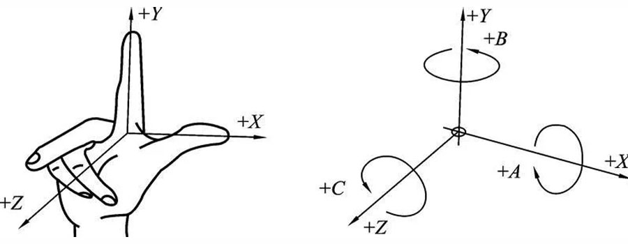
- 2) The definition of the standard coordinate system The standard coordinate system is a rectangular coordinate system, as shown in Figure 2-1-1 (a), according to the right-handed rectangular coordinate system, the thumb, index finger and middle finger of the right hand represent X, Y and Z respectively The direction of the three rectangular coordinate axes; as shown in Figure 2-1-1 (b), the direction of rotation is according to the right-hand spiral rule, four fingers follow the direction of rotation of the axis, and the thumb and the coordinate axis are in the same direction as the positive rotation of the axis, and vice versa For the reverse rotation of the axis, A, B, and C in the figure represent the rotation directions around the three coordinate axes of X, Y, and Z, respectively.
- 3) The definition of positive and negative of the coordinate axis The direction that increases the distance between the tool and the workpiece is specified as the positive direction of the axis, and vice versa as the negative direction of the axis.
2. The method for determining the coordinate axes of the machine tool.
The Z axis represents the main shaft that transmits cutting power. The X axis is parallel to the clamping plane of the workpiece. Generally, the horizontal position is taken. Naturally, the direction of the Y axis can be determined.
1) Lathe coordinate system
The Z coordinate axis is coaxial with the main axis of the lathe, and the lateral movement direction of the tool is the direction of the X coordinate axis
2) Coordinate systems of CNC machine tools
Two coordinate systems of CNC machine tools
CNC machine tool coordinate system has machine tool coordinate system and workpiece coordinate system, of which workpiece coordinate system is also called programming coordinate system.
Machine tool coordinate system
Machine tool coordinate system XYZ is the coordinate system set by the manufacturer on the machine tool, and its origin is a fixed point on the machine tool, which is used as the motion reference point of the moving parts of the CNC machine tool. The origin is the intersection of the end face of the chuck and the axis of the spindle; in a general CNC vertical milling machine, the origin is the intersection of the extreme positions where the moving parts move in the opposite directions of the X, Y, and Z coordinate axes, that is, the workbench in this state On the front left corner.
Workpiece coordinate system The purpose of setting the workpiece coordinate system XpYpZp is for programming convenience. The principle of setting the origin of the workpiece coordinate system should be selected as far as possible on the design basis and process basis of the workpiece.
The direction of the coordinate axis of the workpiece coordinate system is consistent with the direction of the coordinate axis of the machine tool coordinate system. In a CNC lathe, as shown in Fig. 1, the origin Op point is generally set at the intersection of the right end surface of the workpiece and the spindle axis. In CNC milling machines, as shown in Figure 2, the origin of the Z axis is generally set on the upper surface of the workpiece.
For asymmetric workpieces, the origin of the X and Y axes is generally set on the left front corner of the workpiece; for symmetric workpieces, X The origin of the Y axis is generally set at the intersection of the symmetry axis of the workpiece.
Absolute and relative coordinates
1) Absolute coordinate notation
The coordinate value of the tool movement position is expressed as the distance relative to the origin of the coordinate. This coordinate representation is called absolute coordinate representation. Most CNC systems use absolute coordinate programming with G90 instructions.
2) Relative coordinate notation
The coordinate value of the tool movement position is expressed as an increment relative to the previous position coordinate, that is, the difference between the absolute coordinate value of the target point and the absolute coordinate value of the current point.
Most CNC systems use the G91 command to indicate relative coordinate programming. Some CNC systems use X, Y, and Z to indicate absolute coordinate codes, and U, V, and W indicate relative coordinate codes. Two kinds of coordinate notation programming.
Link to this article: CNC Machine Coordinate System
Reprint Statement: If there are no special instructions, all articles on this site are original. Please indicate the source for reprinting:https://www.cncmachiningptj.com/,thanks!
 PTJ® provides a full range of Custom Precision cnc machining china services.ISO 9001:2015 &AS-9100 certified. 3, 4 and 5-axis rapid precision CNC machining services including milling, turning to customer specifications,Capable of metal & plastic machined parts with +/-0.005 mm tolerance.Secondary services include CNC and conventional grinding, drilling,die casting,sheet metal and stamping.Providing prototypes, full production runs, technical support and full inspection.Serves the automotive, aerospace, mold&fixture,led lighting,medical,bicycle, and consumer electronics industries. On-time delivery.Tell us a little about your project’s budget and expected delivery time. We will strategize with you to provide the most cost-effective services to help you reach your target,Welcome to Contact us ( [email protected] ) directly for your new project.
Link to this article:CNC Machine Coordinate System
Reprint Statement: If there are no special instructions, all articles on this site are original. Please indicate the source for reprinting.:Cut Wiki,Thanks!^^
