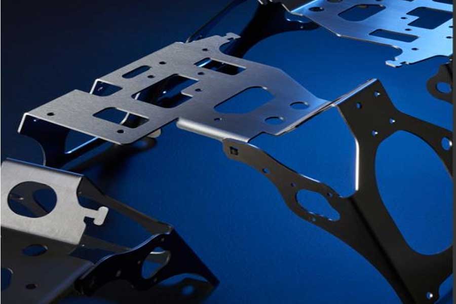
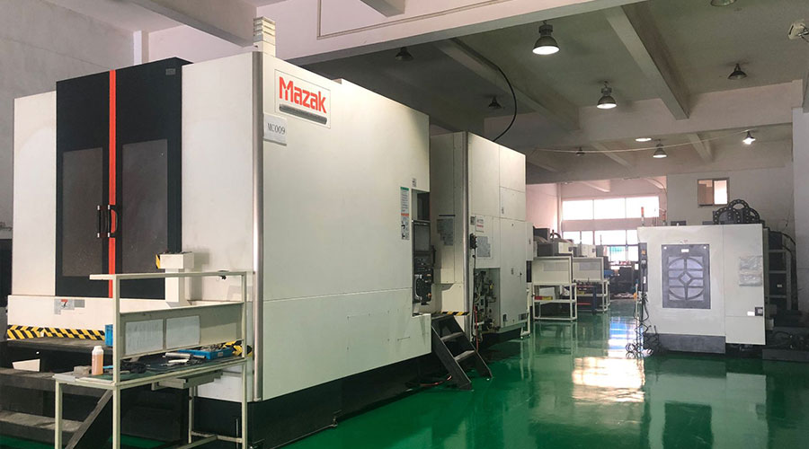
If you walked into the bending machine department of a manufacturer 20 years ago, you would see a very different picture. A machine produces a variety of new, low-quality jobs in a shift, but it takes most of the time to set up, and in fact there is very little time to bend good parts.
The machine setup itself was also different 20 years ago. In many workshops, in the bending process, multiple punches and die sets are configured so that the operator can (ideally) complete a complex part in one setup, which is still rare. Such setting takes time, which requires larger batches. The setup personnel must also be able to visualize the sequence. Usually, it makes sense to divide the forming operation into several simpler settings.
Bending is not unheard of, but it is not as common as it is today, thanks in large part to software. Offline bending programming and simulation have led this development, but software is not the only problem. If it cooperates correctly with other parts (good communication, tools, materials, adaptive bending and tool change automation), the result is that the bending operation will take almost all of the time to form a good part and ultimately make money.

Seems simple
A person who is not familiar with bending machines may look at the bending device and wonder what makes it so complicated. However, even if it is a relatively simple two-station setup, with two dies adjacent to each other, even bending an ordinary box is more complicated than it looks.
For each die tool, the operator needs to consider the height of the inner box or the height of the flange, and ensure that the height of the punch, the width of the indenter and the daylight (the space between the punch and the mold surface when opened) can be accommodated. However, when you introduce the second station (which is necessary when forming boxes with different lengths and widths), you need to consider the length of the unformed flange to ensure that it does not interact with the adjacent work station. Bit collision.
The most experienced bending operator can solve this problem in mind. But what about parts with multiple flanges in different directions and different angles? What if you have a series of positive and negative turns? All these have caused serious complexity.
Another seemingly simple aspect of bending involves closing height. Similarly, suppose you have two tool stations, one with a narrow V-mode and the other with a much wider V-mode; both bend the same material at a 90 degree angle, but the wide V-mode produces a larger radius . However, to produce a larger radius, the punch must be lowered further into the mold space, which will cause a collision of the tool set with a narrow V-shaped mold.
The closing height of the tool can be made into a normal height, or it can be filled with gaps to match. In any case, simulation software can reveal these complexities before the job reaches the bend.
Operators and bending order
If the operator receives a complex bending job involving multiple bends in multiple directions, the part may only be bent in one way, or at most only a few ways. As part geometry becomes simpler and simpler, the number of bending sequence options usually increases. In other words, there are many ways to bend parts.
Today’s software usually selects the best bending sequence for the machine, tool, and application. That is, those who program should never throw work on those who set up the machine and bend it. Bending is a collaborative effort. Modern software combines the geometry and characteristics of the tools and machines that will be used on the brake during the bending process (e.g. minimum and maximum axis movement). However, the operator is still the person who switches tools and manipulates the workpiece between curves.
There are too many to mention, and the inconvenience of moving between the elbow and the tool station will make the operator’s work difficult. Assuming that the part needs to be turned in the Z direction, if there is a punch and die obstruction, this is an impossible task. Therefore, the operator needs to slide it laterally, pull it out of the working envelope, flip the part, and then align it correctly with the back gauge. This is feasible, but it is certainly not efficient or ergonomic, and the operator is likely to mark the part. The key components of cosmetics may need to be reprocessed or even scrapped. Through a quick dialogue between the programmer and the operator, all these situations can be avoided.
Also, over the years, simulation packages have become more intelligent, so it is not common to develop bend sequences full of awkward movements. Now, the software usually finds the best way the operator can bend the workpiece. In any case, healthy communication between programmers and operators is still the most effective way to get the most benefit from bending operations.
Backgauge technology also plays a role here, and Backgauge motion is now simulated along with the tool. Years ago, the backgauge was a flat surface and moved along a limited number of axes. Nowadays, multi-axis backgauges can move fingers independently in multiple directions. Modern offline simulation software not only provides measurement options, but also allows you to view the bend before and during the bend, simulate springback and warn of potential collisions.
The backgauge paddles themselves provide multiple contact points for the operator, and the machined grooves on these paddles can support the workpiece. The finger shape of the backgauge (including custom fingers designed for a specific job) can be imported into the simulation software, so that the programmer can catch collision or interference issues before making the fingers and starting the job.
Likewise, no matter how comprehensive the virtual simulation becomes, communication is still important. After all, the operator is the person who slides parts onto those backgauges every day.
Optimize settings
Consider a part where one downward flange is flanked by two upward flanges. The two upward flanges have a short bending length and the downward flange has a long bending length-but all three are on the same bending line. Older versions of offline software usually create three stakes, one for the flange on the left, another for the right, and the last for the longer elbow in the middle.
This can work, but the device also occupies three bending stations along the length of the bed. Generally speaking, the more molding that can be completed in fewer stations, the more flexible and effective the molding sequence will be.
In this case, one workstation can form the two upward flanges that share the same bending line. It consists of a punch and two segmented molds, with enough space between them to leave a gap in the middle flange. Then the second station will form the central flange. Workpieces previously formed in three stations can now be formed in two, leaving more space on the machine bed for other stations to handle other bends in the part. The more types of bends that can be formed by the setting, the higher the efficiency of the bending operator.
This is just a simple example, even before bending simulation is available, optimizing this staged setup is not out of reach for experienced operators. However, nowadays, software simulation optimizes multiple bending stations to a level, and even for experienced operators, it cannot develop quickly.
Make the results repeatable
Nowadays, both programmers and operators can view the bending simulation and be confident that the simulation reflects reality, and the first part will be a good part. In other words, several other puzzles also need to be installed in place.
First involves the materials. The material with a nominal thickness of 3 mm can vary; sometimes it may be 3.3 mm, and sometimes (more commonly) it may be thinner, only 2.7 mm. Due to the thickness variation, the bending simulation incorporates a conventional bending tolerance window.
In other words, the smaller the bending tolerance, the better the material required. Nowadays, precision bending operations usually select more expensive materials with far fewer variations in thickness and tension. In other words, it is impossible to eliminate all changes. In fact, controlling all the variables in bending may have a negative impact on upstream cutting, especially in terms of material yield. The material may bend differently depending on the grain direction. The change in tonnage is quite small, but the new grain direction can change the inner radius, so it is necessary to change the penetration force of the punch in the die.
In order to manage these changing bending characteristics, programmers often select the “particle constraint” function in the nesting software. Unfortunately, those grain restrictions can reduce material yields. If laser or punching programmers can freely place parts anywhere on the paper, material yield can be increased. However, even in the most advanced bending simulations, this can cause severe damage in certain precision bending applications. The operator can accurately track the simulation, but due to the inconsistency of the grain direction, there will still be problems in the end.
Another problem: adaptive bending. The real-time angle measurement on the bending machine allows the machine to be adjusted even in the face of common inconsistencies (including excessive material thickness, hardness and grain direction changes). Adaptive bending can also use cheaper materials because the system can compensate for material irregularities.
Eliminate differences in the process
Inconsistent bending may be caused by changes in material thickness and tensile force, but inconsistent bending can also occur when the material moves in an unexpected manner during the bending cycle itself. This is especially common in asymmetric part geometries and high-stretch materials, and in molds that wear out at the mold shoulders over time. The material moves inconsistently on the mold shoulder, pulling the bend to one side or the other, resulting in a bad part.
A mold with a special radius on the mold shoulder can help make the bend more consistent by reducing contact stress and allowing the material to bend smoothly into the mold space. Specifically, the radius of the mold shoulder is not constant, but gradually increases as it transitions into the mold cavity. The design reduces friction, thus reducing the chance of this challenging material “jumping into” the mold space during the molding cycle.
Prepare for tool change automation
In the past 20 years, offline programming has eliminated the need for on-machine programming, and related simulations have made tool arrangements that were once considered extremely complex less complicated. The simulation combines the design and movement of the rear baffle plate, and optimizes the staged all-in-one setting, so that the operator can use fewer workstations to form more elbows.
Adaptive bending reduces the need to achieve die confinement in laser cutting or stamping to form a consistent shape. In some applications, adaptive bending restricts particles to meet the decorative requirements of the part (for example, stainless steel panels on kitchen or restaurant equipment).
Finally, mold design helps make molding more consistent, even for materials that are difficult to mold. In the past 20 years, the quality of many materials has improved. If the workshop is to perform precision molding work, the materials that can now be selected can provide smaller thickness and hardness changes, so the bending is more consistent.
Now that the bending becomes so consistent, the forming operation can finally effectively meet the needs of high-product mixed production. But the last contradiction still exists: the tool itself will change.
Tools may be misplaced, dropped or damaged. Depending on the clamping technology of the tool, the position of the punch and die may be slightly offset, cannot be installed correctly, or even installed backwards. In addition, since simulation can now quickly develop even the most complex stage settings, the operator can see various settings on the day’s timetable, from the simplest settings using one or two workstations to span a considerable part of the time The most complex setting.
This challenge laid the foundation for the most significant advancement in the past 20 years: the automatic tool changer bending machine. With the push of a button, the tool will automatically change and be accurately placed in the correct position, thus completely reproducing what appears in the simulation. As the tools are changed, the operator will prepare materials for the next job in stages-today, the size of these jobs may be 12, 5, or even just one piece.
Of course, if the operator needs to spend a lot of time trying out parts, or if the tool station is not optimized, or if the operation does not take into account changes in material properties and grain orientation variables, then automated tool change is meaningless. .
The bending operation of today is very different from 20 years ago, and there is no doubt that there will be more innovations to make the bending more effective. The bending operation can be one of the most flexible operations on the factory floor.
Link to this article: What should I pay attention to when performing the bending process on a modern bending machine?
Reprint Statement: If there are no special instructions, all articles on this site are original. Please indicate the source for reprinting:https://www.cncmachiningptj.com/,thanks!
 3, 4 and 5-axis precision CNC machining services for aluminum machining, beryllium, carbon steel, magnesium, titanium machining, Inconel, platinum, superalloy, acetal, polycarbonate, fiberglass, graphite and wood. Capable of machining parts up to 98 in. turning dia. and +/-0.001 in. straightness tolerance. Processes include milling, turning, drilling, boring, threading, tapping, forming, knurling, counterboring, countersinking, reaming and laser cutting. Secondary services such as assembly, centerless grinding, heat treating, plating and welding. Prototype and low to high volume production offered with maximum 50,000 units. Suitable for fluid power, pneumatics, hydraulics and valve applications. Serves the aerospace, aircraft, military, medical and defense industries.PTJ will strategize with you to provide the most cost-effective services to help you reach your target,Welcome to Contact us ( [email protected] ) directly for your new project.
Link to this article:What should I pay attention to when performing the bending process on a modern bending machine?
Reprint Statement: If there are no special instructions, all articles on this site are original. Please indicate the source for reprinting.:Cut Wiki,Thanks!^^
