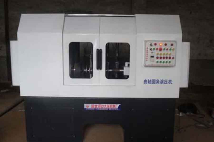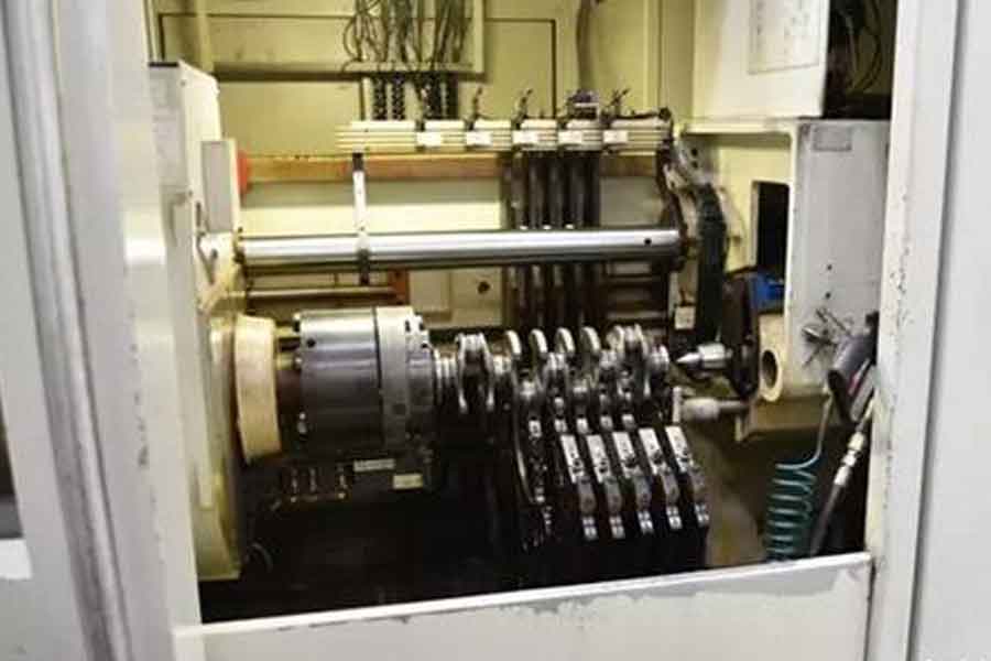
As the core component of the engine, the crankshaft is facing serious challenges in safety and reliability with the development of the engine in the direction of supercharging, high power, and high reliability. The analysis of the principle of crankshaft rolling can effectively improve the fatigue resistance of the crankshaft.
Strength and service life, clarify the application of the equipment used in the rolling process-the crankshaft rolling machine tool, independent research and development puts forward a design plan for the transformation of the crankshaft rolling machine tool, and elaborates the structural principle of the rolling machine tool and its key components in detail , Functional characteristics and quality assurance measures to solve the problems and failures of imported crankshaft rolling machine tools in the process of rolling crankshafts, reduce the maintenance cost of crankshaft rolling machine tools, realize the goal of replacing imports, and ensure the crankshaft rolling machine tools The working stability improves the quality of crankshaft rolling.
The crankshaft is a high-speed rotating long shaft in a car engine. It is one of the main parts in the engine. Among the five major parts of the engine, it is the most difficult part to ensure the quality of processing. The working conditions of the crankshaft are bad. In each cycle of engine operation, there are alternating loads acting on the crankshaft.
These alternating loads act on the crankshaft to cause it to bend, bend, etc., thereby making the crankshaft work ineffective. The failure modes are generally journal wear and fatigue fracture. Among them, fatigue cracks and fatigue fractures caused by alternating stress are often destructive and involve safety.
News reports in this area have attracted great attention from the public. The crankshaft fillet rolling strengthening process is one of the most effective means to improve the fatigue strength of the crankshaft. Almost all of the foreign car engine crankshafts use the fillet rolling process.
1. The Principle Of The Crankshaft Rolling Process
Engines use more crankshaft journals and crankshafts, lower bending rigidity, and anisotropy in the circumferential direction, coupled with the inhomogeneity of materials, and the influence of comprehensive factors such as deformation and residual stress in hot and cold processing, making The bending deformation of the crankshaft is very complicated, and its axis is an arbitrary curve in space. The crankshaft completes the deep rolling process and the straightening process through the rolling process. After the straightening process, the shortcomings of deformation and bending are basically overcome, and the deep rolling process makes the rounded part of the rolled journal surface strengthened Treatment improves the bearing capacity and fatigue strength of the crankshaft. Crankshaft fillet rolling is to plastically deform the surface through the pressure of the rolling mechanism at the transition fillet between the connecting rod neck and the main journal of the crankshaft.
The structure and shape of the fillet surface will change, and the crankshaft fillet The structure at the place is tight, so that residual compressive stress appears in the surface of the crankshaft fillet, which can be offset or partially offset with the tensile stress of the crankshaft during work, thereby improving the fatigue strength; cold work hardening occurs on the metal surface, and the corners are rounded after rolling
The surface layer is a dense layer with high hardness, the material surface has been strengthened; casting defects such as micro pinholes, cracks, and pores on the crankshaft surface are eliminated; the surface quality of the rounded corners is improved, thereby greatly reducing the stress concentration at the transitional corners of the journal , Strengthen the physical properties of the material at the fillet, and significantly improve the fatigue strength of the crankshaft.
2. Transformation Design Of Crankshaft Rolling Machine Tool
In summary, because of the many advantages of the rolling method, this process has become the mainstream process for crankshaft fillet machining, and the rolling machine tool was born. In foreign countries, the technology of crankshaft fillet rolling machine tools has been mature, and rolling machine tools have been widely used, and more and more have replaced the traditional method of turning crankshaft main journal and connecting rod neck round corners with tools on traditional machine tools. However, the crankshaft fillet rolling intelligent flexible processing machine tool is a high-tech numerical control equipment integrating mechanics, electronics, detection technology, and artificial intelligence. At present, the technology and level of production of rolling machine tools in China has a great deal with that of foreign countries. The gap, many core technologies have not yet been truly mastered, so that most domestic crankshaft manufacturers import this type of machine tools from abroad.
However, after several years of use, there are technical upgrades and the problems of how to solve the problems. Now take a German imported crankshaft rolling machine tool of Guangxi Yuchai Crankshaft Co., Ltd., a school-enterprise cooperative enterprise, as an example for the following analysis.
2.1 The Existing Problems Of The Crankshaft Rolling Machine Tool Before The Transformation
- – After the imported crankshaft rolling machine has been used for nearly 20 years, the system has no response and cannot work normally.
- – The imported crankshaft rolling machine tool can only roll four-cylinder crankshafts during normal operation, and cannot meet the order for rolling six-cylinder crankshafts.
- – The imported crankshaft rolling machine cannot guarantee constant pressure rolling when the crankshaft rotates at 60 r/min, which affects the quality of crankshaft rolling.

2.2 Design Plan After Transformation
According to the current user’s equipment situation, on the basis of comprehensively considering factors such as reliability, performance, function, and price, the following transformation plans are proposed.
2.2.1 CNC Spare Part
- – Use Siemens 840DSL CNC system to replace the original CNC system; the system host is 840DSL NUC 720.3 HMI: PCU5.5-C man-machine interface; Chinese display; USB interface; with OP010 10.4 “TFT color LCD display and operation panel; with 19 “MCP machine control panel with spindle and feedrate override switch.
- – Feed driver and motor: Use Siemens all-digital S120 driver and 1FT7 AC servo motor to replace the original machine tool X, Z, X1, Z1, SP, these five feed drivers and motors, with a full set of Siemens cables. The motor type selection is not less than the original servo motor torque, and the motor configuration is 1FT7034 2 T units, 1FT7062 2 units, and 1FT7102 1 unit. Replace the 4 original machine tools with ordinary AC motors for fine-tuning the position of the rolling heads with Siemens AC servo motors, and select 4 1FT7034 motors according to the original motor power.
- – Keep the original external encoder of the main shaft and equip the corresponding encoder interface conversion module.
- – Adopt S7-300 PLC programmable controller, I/O configuration, reserve 10% margin, I/O module is equipped with terminal connector. Use PLC to realize all logical sequence control tasks of the machine tool, including oil pump, lubrication, workpiece feeding, workpiece clamping loosening, tailstock center control, rolling head feed control, external protection and other controls.
- – Keep the original left and right two sets of internal and external roller detection sensors for a total of 4 rolling heads, and connect the sensor signals to the PLC to monitor the damage of the rolling tool and the rotation of the rolling tool. According to the input signal frequency of the sensor, it is judged whether the working condition of each indenter is normal. If there is an abnormality, the processing will be stopped and an alarm will be issued.
- – Compile the manual decomposition interface of each component action, including the separate manual interfaces of the left and right two sets of rolling heads, and the separate manual interfaces of the tailstock center, workpiece feeding, headstock and other components.
2.2.2 Machine Tool Electric Cabinet
- – Re-make the electrical control cabinet of the machine tool, use the Rittal brand for the electrical cabinet shell, redraw the layout of the electrical cabinet, reinstall the electrical components according to the layout, and re-wiring in the electrical cabinet to ensure that the wiring is neat and beautiful, and the terminal labels are regular, Clear and consistent with the installation diagram. The servo motor cable and feedback cable use Siemens original cables. Avoid parallel wiring between power lines and signal lines in the electrical cabinet. The numerical control system and the feed drive part are equipped with isolated power supplies. The drive power inlet is equipped with a Siemens AC inlet high-frequency reactor to reduce the interference to the power grid. An isolation transformer is added to the power supply line of the numerical control system. Ensure that all devices are well grounded.
- – Select the appropriate wire diameter according to the size of the conducted current. The color of the wire is selected according to the national electrical wiring standards for machine tools. The control wire DC is the blue wire, AC is the red wire, the power wire is the black wire, and the ground wire is the The yellow and green wires, all grounding wires in the electrical cabinet are separately collected with the grounding copper bar in the electrical cabinet to ensure a good grounding of the entire electrical cabinet.
- – The main related second-class control components in the control cabinet all use Schneider and Siemens components. The outlets of the electrical cabinet are arranged in the order of the machine parts, and the industrial rectangular aerial plug connection is used to facilitate the relocation of the machine tool in the future. The electric control cabinet is equipped with a 2 kW special electric cabinet air conditioner.
2.2.3 Hydraulic System
The hydraulic system of the machine tool is the core of the machine tool control and guarantees the machining accuracy of the entire machine tool. The actuator includes a hydraulic clamping unit, a servo force unit, and a detection unit (including spindle position detection and chuck pressure detection). The rolling pressure of the original machine tool is variable pressure processing, that is, the pressure applied to the connecting rod neck is different according to the rotation angle of the crankshaft. The processing rolling pressure on the connecting rod neck is a square wave curve. The rolling force control of the original machine tool consists of 4 Rexroth servo valves model 4WS2EM10-45/20B2T315Z8DM, 4 Rexroth servo amplifier boards model VT1600S3X and related auxiliary control boards. The original servo valve, amplifier board and auxiliary control board have been discontinued for many years, and there is no supply of spare parts. This transformation will upgrade the complete hydraulic pressure control system. The configuration of the machine tool servo valve after the transformation is based on the pressure and flow parameters of the original servo valve, and the Rexroth 4WRPNH10 servo valve is selected. Its function is explained as follows.
IAC-R valve (integrated axis controller based on high-response valve) is a digital high-response valve with integrated axis controller, which has the following functions: flow control, position control, pressure control, p/Q function, alternating Position pressure and position/force control, NC function, can choose to provide control value through analog interface or field bus interface, actual value signal can be provided through analog interface, in addition can also be read out through field bus, controller parameters are set through field bus ; For safety reasons, the bus/controller and power components (output stage) use independent power supply voltages. Users can use the debugging software WinHPT to program and diagnose the parameter setting box functions, and easily manage data on the PC. There are other available functions: ramp function generator, error signal output 24 V (such as switching signal to PLC/logic and other valves), control output adjustment, dead zone compensation, zero correction, valve bending compensation, friction compensation, Direction-dependent gain. Digital integrated control electronics can be used for the following fault detection: cable disconnection sensor, undervoltage, temperature of integrated electronics, communication error.
The servo valve control adopts the same PROFIBUS bus control method as Ingersoll Company. The control setting of the amplifier is transmitted from the PLC of the CNC system to a servo valve controller through the bus, and the corresponding clamps are made on the CNC system panel. The head pressure setting interface allows the high and bottom pressure values of each chuck to be set according to the process requirements when processing different workpieces. The change of the high and low pressure value is read into the position signal of the spindle encoder by the PLC, the internal calculation of the PLC makes the crankshaft different angles send out the corresponding high and low pressure setpoints, and the action of the servo valve is controlled by the amplifier to make the pressure of the chuck follow. When the given value changes, a pressure sensor is installed on the hydraulic pipeline of each chuck, and the signal of the pressure sensor is connected to the amplifier, so that the amplifier forms a closed-loop pressure control system, thereby ensuring the accuracy of pressure control.
2.2.4 Rolling Pressure Monitoring And Recording System
Install a new sensor at the position where the pressure sensor is installed at the back of the original chuck to monitor the actual pressure. The pressure sensor uses Rexroth products with signal cables and amplifiers. An industrial computer is installed for pressure monitoring and pressure recording devices of the four chucks of the crankshaft rolling machine. The industrial computer uses Advantech products, and the industrial computer is equipped with a signal acquisition board, which connects the 4 pressure sensor signals to the acquisition board. At the same time, relevant interface signals are reserved between the industrial computer and the numerical control system. Edit pressure monitoring and recording system software. In order to facilitate the retrospective query of the rolling parameter data of each part, the part number must be entered on the industrial computer interface before each part is processed and the system can only start the processing program for processing after confirming. Before each part is processed, a pressure test is required. If the pressure test fails, the industrial computer will send out an alarm signal, and the alarm signal will be sent to the CNC to stop the machine tool to ensure the pass rate of the part processing. In the machine tool processing, the industrial computer will automatically record the pressure value of each chuck and draw the corresponding curve according to the set time interval and save it.
2.3 Application Effect After Transformation

- – The operating reliability of the modified crankshaft rolling machine tool is improved, the equipment failure rate is reduced, and the equipment meets the normal processing of the product.
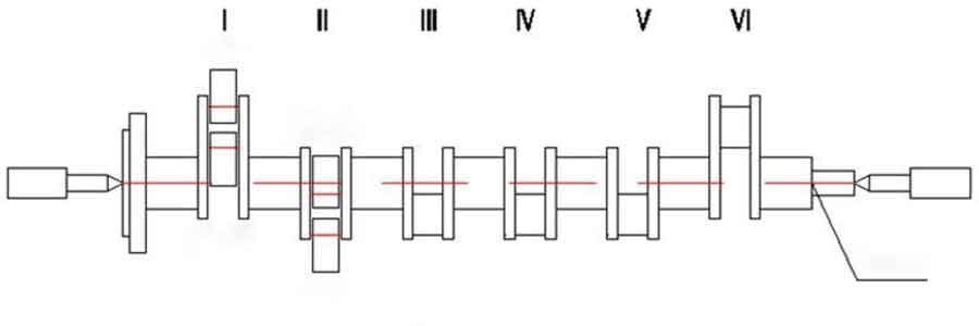
- – To meet the technical requirements of crankshaft rolling, when the crankshaft is rotating, as the position of the neck changes, the rolling pressure follows the change of the crankshaft motion trajectory and changes, and a certain constant rolling pressure is maintained. As shown in Figure 1, I and VI: the high-pressure angle is 60° to 300°, and the other angles are low-pressure; II and V: the high-pressure angle is 180° to 60°, and the other angles are low-pressure; III and IV: the high-pressure angle is 300 ° to 180 °, the other angles are low pressure. When rolling, because the crankshaft’s neck I pushes the upper rolling wheel to deviate from the center of rotation at 60° to 300°, the pressure of the upper rolling wheel is high, and the pressure of the lower rolling wheel is low. We read the rotation angle of the crankshaft in real time through the numerical control system. The rolling wheel of the I neck at the position of 60° to 300° sends low pressure, and the lower rolling wheel sends high pressure. In the same way, for the II neck at the position of 180° to 60°, the rolling wheel sends low pressure, and the lower rolling wheel sends high pressure. This ensures that the rolling pressure on the outer circle of the neck is basically the same in all directions, thereby greatly improving the quality of the product.
- – After the upgrade and transformation, the existing problems of the original imported crankshaft rolling machine tool have been solved. It can roll both four-cylinder crankshaft and six-cylinder crankshaft during operation.
3. Conclusion
In view of the failure problems and upgrade requirements of the crankshaft rolling machine imported by the user after several years of use, according to the above-mentioned modification design scheme, the equipment overhaul cost is greatly saved. The modified crankshaft rolling machine meets the process requirements of crankshaft rolling. When rolling the crankshaft fillet, the pressure of rolling follows the change of the motion trajectory of the crankshaft. That is, when rolling the neck, because the neck is not on the center of rotation, the rolling is variable pressure rolling.
The rotation position of the neck is detected by the numerical control system, and then the pressure valve is controlled to achieve constant pressure in all directions of the neck, thereby improving the production accuracy of the crankshaft rolling (to make the rolling deformation of the 0.8 m long six-cylinder crankshaft as a whole <0.02 mm) and the overall quality, reduce the scrap rate of crankshaft rolling (scrap rate <0.4%), ensure the stability of the crankshaft rolling machine, and reduce the failure rate of equipment. It is difficult to guarantee domestic equipment at present, and it is for future maintenance , Upgrade, expansion, communication, etc. provide convenience.
Link to this article: The Application Principle And Modification Design Plan Of Crankshaft Rolling Machine
Reprint Statement: If there are no special instructions, all articles on this site are original. Please indicate the source for reprinting:https://www.cncmachiningptj.com/,thanks!
 PTJ CNC shop produces parts with excellent mechanical properties, accuracy and repeatability from metal and plastic. 5 axis CNC milling available.Machining high-temperature alloy range inclouding inconel machining,monel machining,Geek Ascology machining,Carp 49 machining,Hastelloy machining,Nitronic-60 machining,Hymu 80 machining,Tool Steel machining,metal enclosur etc.,. Ideal for aerospace applications.CNC machining produces parts with excellent mechanical properties, accuracy and repeatability from metal and plastic. 3-axis & 5-axis CNC milling available.We will strategize with you to provide the most cost-effective services to help you reach your target,Welcome to Contact us ( [email protected] ) directly for your new project.
Link to this article:The Application Principle And Modification Design Plan Of Crankshaft Rolling Machine
Reprint Statement: If there are no special instructions, all articles on this site are original. Please indicate the source for reprinting.:Cut Wiki,Thanks!^^
